Juinper Labs Design
Lab Design
ACX1100 uses your home network’s VLAN 13 as its WAN (internet access). VLAN 13 is also connected to a GNS3 virtual machine for future use.
- Logical Router Core (LRC): Only logical system directly connected to the ACX1100; serves as the core router. All other logical systems use it as a central “hop” to the rest of the network.
- Logical Router 1 (LR1): Stand-alone logical system.
- Logical Router 2 (LR2): Stand-alone logical system.
- Logical Router 3 (LR3): Stand-alone logical system with an extra port used for connection to an external ARM64 SBC running FRR.
Each node has an additional /32 loopback address.
ACX1100 will provide internet/home-network access via source NAT to all logical systems and their networks using the NAT pool 172.20.13.200–172.20.13.205.
Logical Systems Connection Diagram
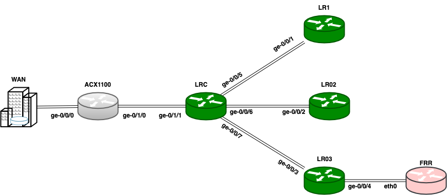
| Device | Local Port | Local IP | Peer Device/Port | Peer IP |
|---|---|---|---|---|
| ACX1100 | ge-0/0/0 | 172.20.13.1/24 (VLAN 13) | WAN (home network VLAN 13) | 172.20.13.254/24 (gateway) |
| ge-0/1/0 | 10.0.0.1/30 | LRC (ge-0/1/1) | 10.0.0.2/30 | |
| lo.0 | 100.0.1.1/32 | — | — | |
| Logical Router Core (LRC) | ge-0/1/1 | 10.0.0.2/30 | ACX1100 (ge-0/1/0) | 10.0.0.1/30 |
| ge-0/0/5 | 10.0.1.2/30 | LR1 (ge-0/0/1) | 10.0.1.1/30 | |
| ge-0/0/6 | 10.0.2.2/30 | LR2 (ge-0/0/2) | 10.0.2.1/30 | |
| ge-0/0/7 | 10.0.3.2/30 | LR3 (ge-0/0/3) | 10.0.3.1/30 | |
| lo.123 | 100.1.2.3/32 | — | — | |
| Logical Router 1 (LR1) | ge-0/0/1 | 10.0.1.1/30 | LRC (ge-0/0/5) | 10.0.1.2/30 |
| lo.1 | 100.1.1.1/32 | — | — | |
| Logical Router 2 (LR2) | ge-0/0/2 | 10.0.2.1/30 | LRC (ge-0/0/6) | 10.0.2.2/30 |
| lo.2 | 100.2.2.2/32 | — | — | |
| Logical Router 3 (LR3) | ge-0/0/3 | 10.0.3.1/30 | LRC (ge-0/0/7) | 10.0.3.2/30 |
| ge-0/0/4 | 10.0.4.1/30 (DHCP-server) | FRR arm64 (eth0, DHCP-client) | 10.0.4.2/30 | |
| lo.3 | 100.3.3.3/32 | — | — | |
| FRR (arm64 SBC) | eth0 | 10.0.4.2/30 (DHCP-client) | LR3 (ge-0/0/4) | 10.0.4.1/30 |
| lo0:10 | 200.4.4.4/32 | — | — |
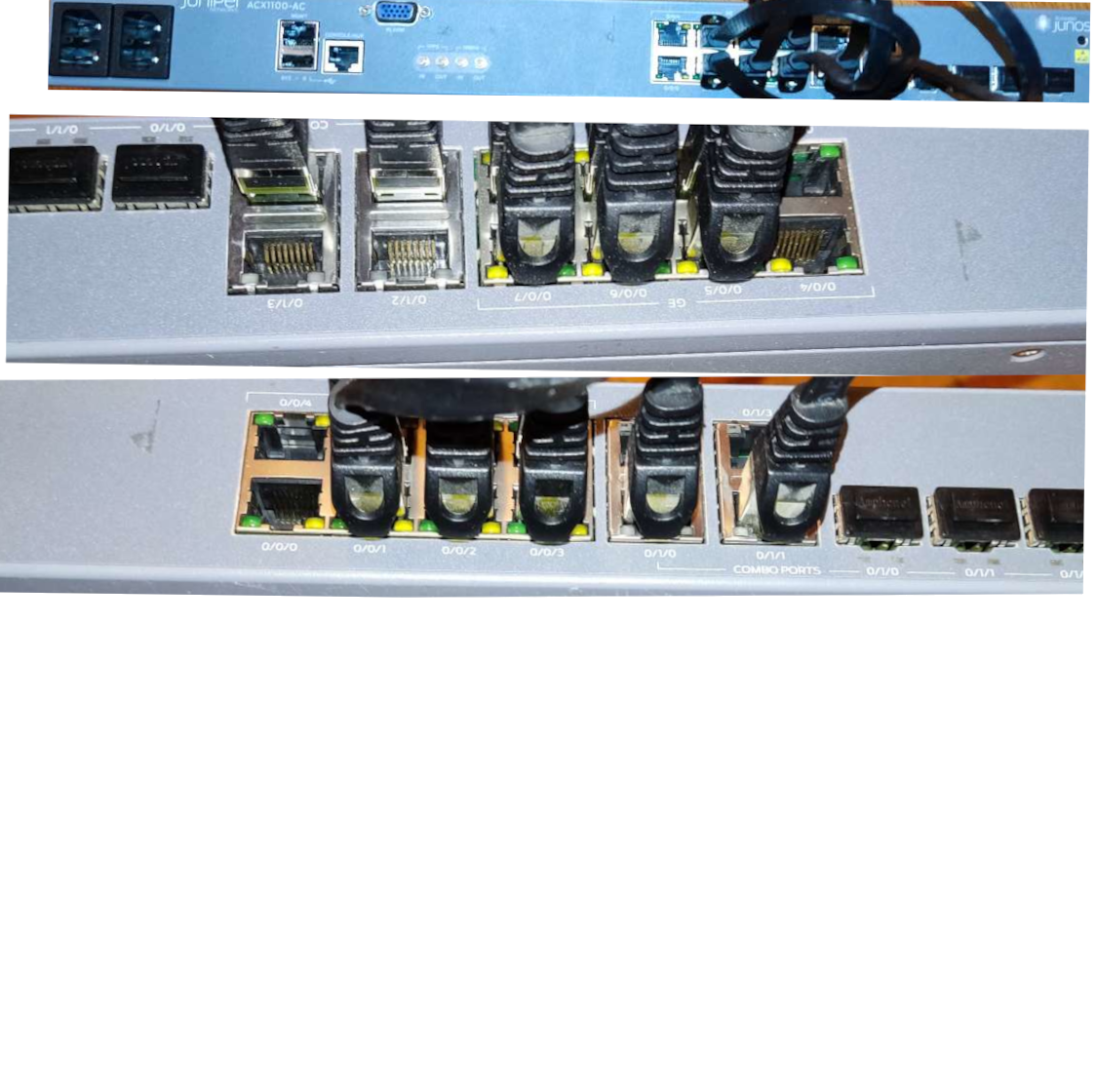
Physical Cabling for Logical Systems